Cutouts in SolariaPCB
Attaching a component to a heat sink that is bonded to the surface of the board is a common way of conducting the heat away from a component. The leads of the component need to get attached to the board surface so there needs to be cutouts in the heat sink to allow the leads to be directly soldered to the board surface. These heat sinks can get quite complex in shape with a heavily populated board. The new cutout feature in SolariaPCB provides many ways to create cutouts in the board.
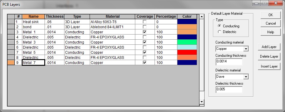
In the PCB Layers dialog above, two layers were added to the top surface of the board. The first is the aluminum heat sink and the second the heat sink bond.
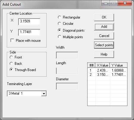
In the Add Cutout dialog above, four methods are provided to define and locate a cutout. A cutout can be rectangular by defining the Width and Length then selecting its location on the board or by selecting two diagonal points on the board with the mouse. The cutout can be circular by defining its Diameter then selecting its location on the board. The cutout can also be any arbitrary shape by selecting the Multiple points option, hit the Select points button then select points on the board to define its shape.
A cutout can be a hole through the entire board by selecting the Through Board radio button. Or the cutout can be on one side and extend down to an internal layer in the board.
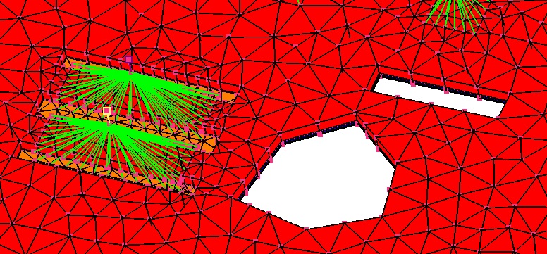
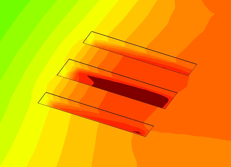
The picture above shows a board with two Cutouts through the board and three in the lead area of two components that go through the heat sink and bond layers exposing the board surface. One of the through the board Cutouts was created by selecting six points and the other using the Diagonal option.
In looking closer at the component thermal representation, resistors representing the leads along the two sides of the component automatically get attached to the board surface, as seen in the Cutouts. The components are defined as bonded. So the resistors from the component Case node to the surface under the component automatically get attached to the heat sink surface.
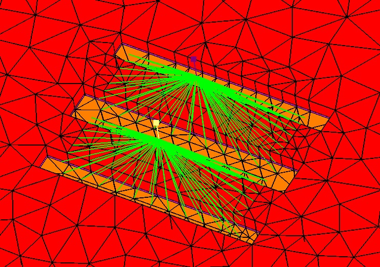
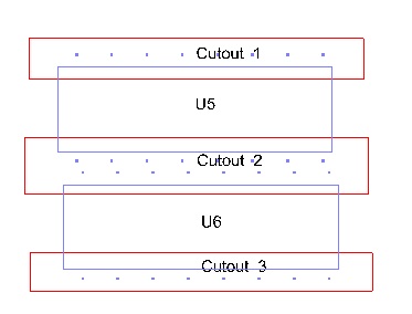
The picture above shows the placement of the three Cutouts in the areas of the components U5 and U6.
As you can see, there are no black boxes in SolariaPCB. We make sure that you understand how everything is thermally represented in the thermal model. We don't feel comfortable using software that hides how it works and we don't feel that you would be either.


